Introduction and Background
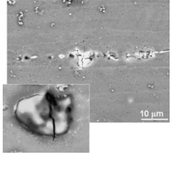
Aluminum Alloy-T6 7075 (AA 7075) is an aluminum alloy whose composition is composed largely of 5.1-6.1% zinc, 2.1-2.9% magnesium, 1.2-2.0% copper and <0.5% Iron, Silicon, Manganese, Chromium, Zirconium and Titanium. During the material processing and hot rolling stages of the alloy, it is common for μm-sized particles to become ingrained in the material matrix. Rollett Et al. have stated that these particles contribute up to 2% of the total volume of the matrix. Deformation of the alloy can cause these particles to either crack or become fully detached from the matrix. When the alloy is eventually put under stress, these cracked particles and the areas where the particles have detached can cause the matrix itself to crack. A crack in the matrix combined with continued stress can cause a failure within the section of the alloy.
Motivation
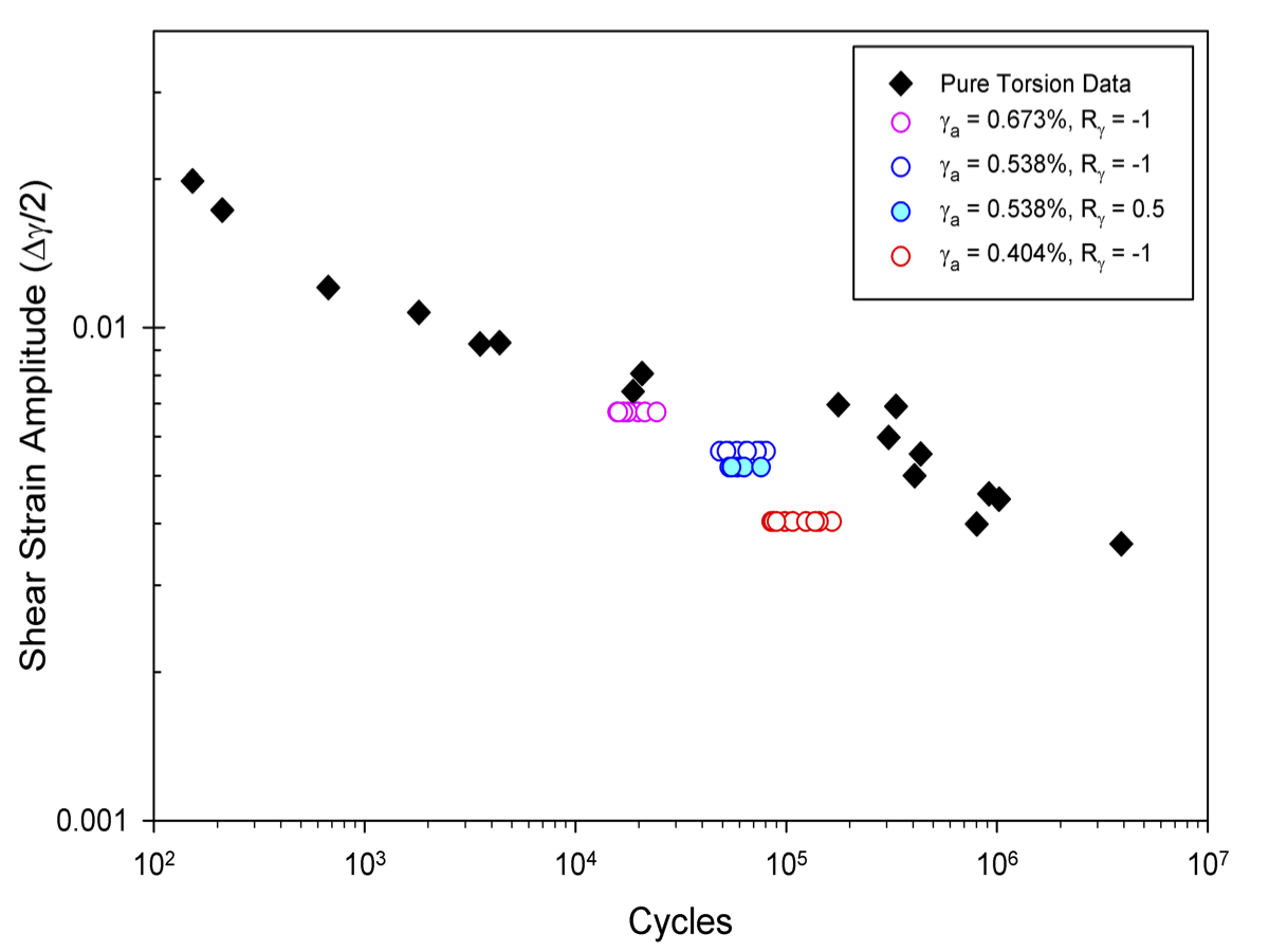
The current fatigue life calibration has very conservative shear life predictions. We hope to correct this by examining damage in both shear and unaxial loadings for AA 7075 dependent upon the anisotropic distribution of the constituent particles. This project would be the first to use a multi-stage approach with a low cost informatics framework to aid high cycle fatigue life predictions. All later references to shear loading will be taken in the XY plane i.e. in the plane shown in all microstructure images. The uniaxial loading conditions will be taken along the rolling direction, as is common in literature. Both loads are at 0.002 strain amplitude.
Problem Statement/Objectives
We want to be able to predict the life-limiting FIP for a given particle cluster, load amplitude, and load biaxiality. We will be using the Fatemi-Socie FIP to quantify fatigue lives, defined by . In this equation $\sigma$ is the tension on the maximum shear plane, $\sigma_y$ is the cyclic yield stress, $\frac{\gamma}{2}$ is the maximum plastic shear and k is a calibration constant for multi-axial fatigue (usually taken as 0.5). In this particular project, we have investigated the non-local averaged FIP surrounding the particles. An averaging volume of ~5% particle volume is used. The maximum of these FIP determines the life-limiting crack extension into the matrix.
Data
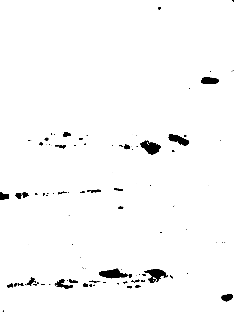
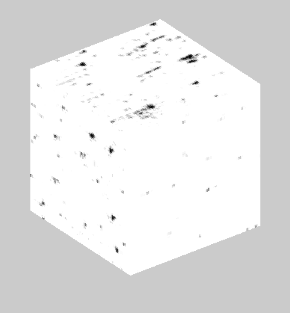
We have 6 microstructure images taken from multiple samples all in the short transverse plane. A 21x21x21 microstructure created from delta microstructures was used to train the 6 strain tensor MKS models. The six microstructure images range from 100x100 to 1200x1200 $\mu$m were used in the creation of 10 200x200x200 element microstructure reconstructions.
Example Microstructure Image:
 3D Reconstruction:
Workflow
In general, our modeling process began with training our model using delta microstructures. We then tested our model under the different loading conditions and created quantifications of error to understand issues with the model. The errors for the 5 21x21x21 validation microstructures can be seen here.
Validation Errors for Uniaxial Loading:
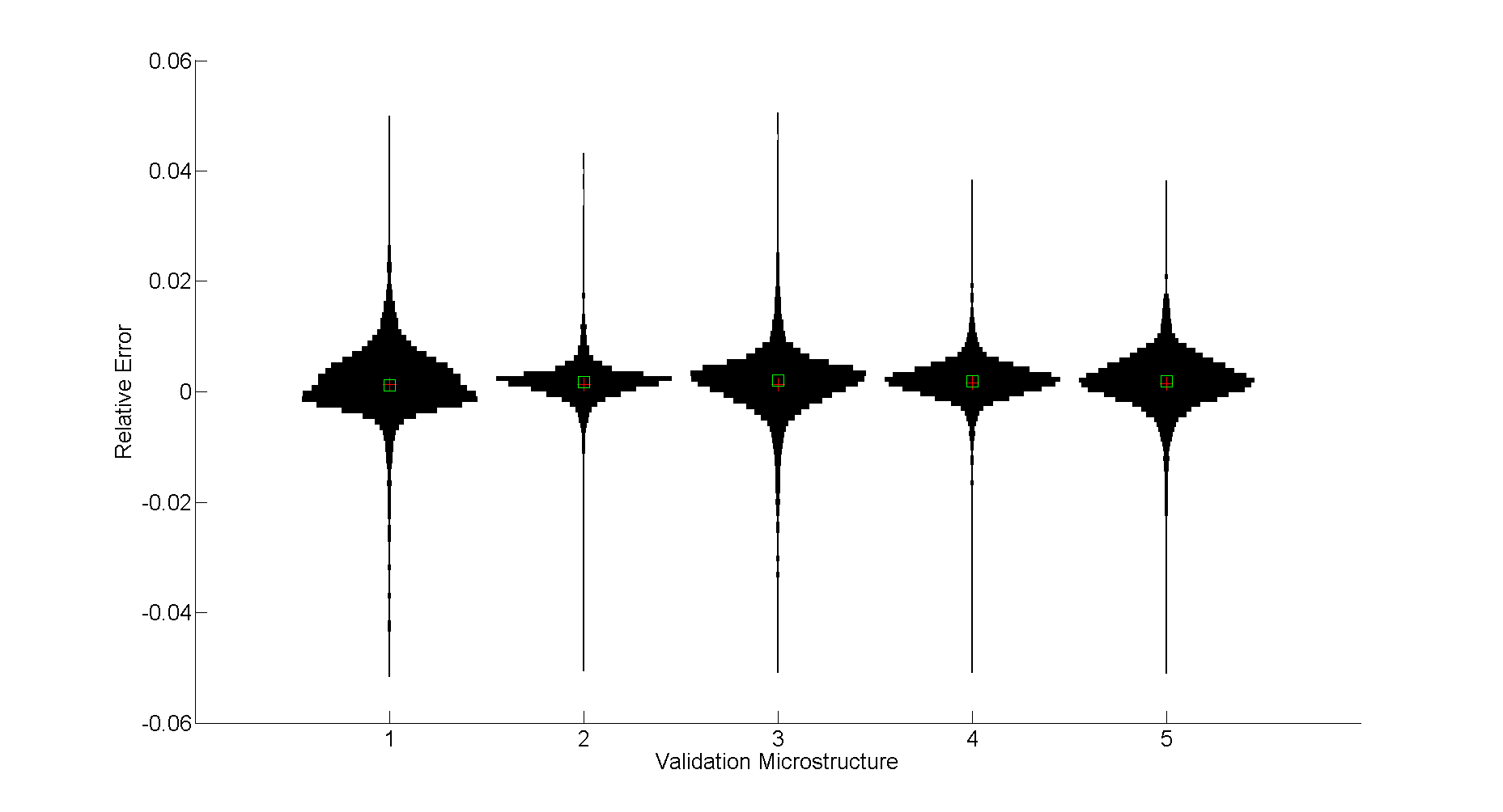 These error quantifications were used to verify the model before we predicted strain fields for the large microstructure reconstructions. We finally predict FIPs using MKS method on several very large reconstructions. The branching nature of our workflow is shown below.
Workflow:

For more information on the specific implementation of MKS we used and the process of training and using influence coefficients, please see (here)
Project Challenges
One of the first challenges we encountered was simply upon how to define distance measured to the nearest particle for the purposes of binning error and FIP distributions. Our original plan involved using Manhattan distance measurements (due to the constant strain in each element), however our error quantifications found this to be a non-desirable way to measure distance. Therefore we ended up deciding on using euclidean distance for our measurements. When we proceeded to the training section using delta microstructures in the MKS method, we initially used different Poisson ratios between the particle and matrix phases to a negative outcome on our predictions. After changing the Poisson ratio for the particle phase to match the matrix, our results improved drastically.
For further explanation of the issues and rectification, please read (this)
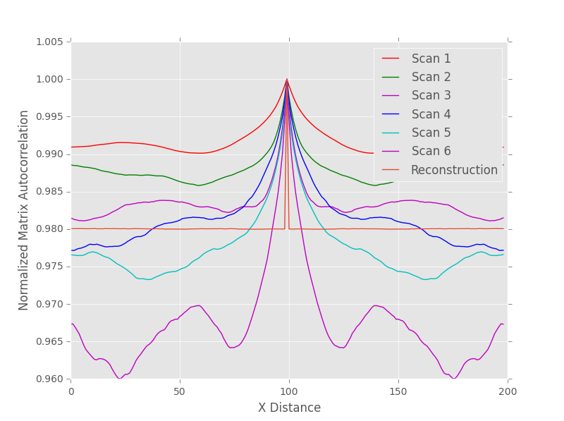
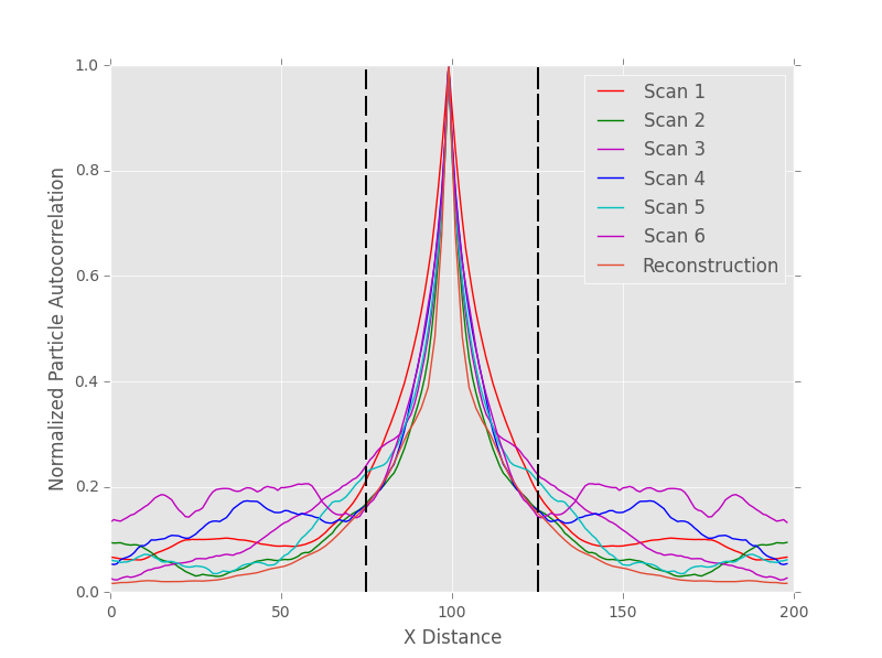
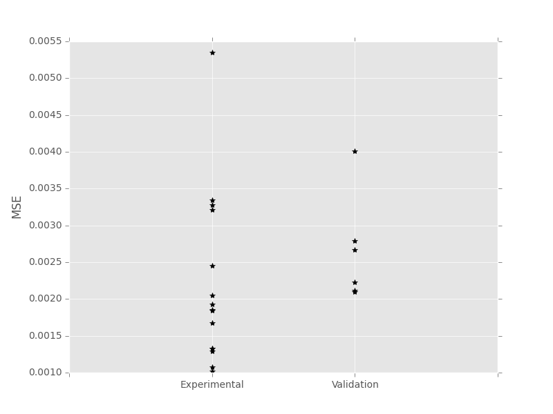
To demonstrate the applicability of our FIP predictions to the problem at hand, we compared a random particle microstructure and reconstruction microstructure to the six microstructure scans using 2 point statistics. Since we only need one correlation to fully describe the 2-phase microstructure we first used the matrix auto-correlation. This erroneously indicated that the difference between the random and reconstructions were less than the difference between the different scans. The was fixed by comparing truncated 2 point statistics based on the average stringer length and using the particle auto-correlation instead. The difference in sensitivity is readily apparent in the differences between the following two images.
Random Particle Matrix Auto-Correlation:
 Trimmed Reconstruction Particle Auto-Correlation:
 MSE for the Randomized Microstructure:
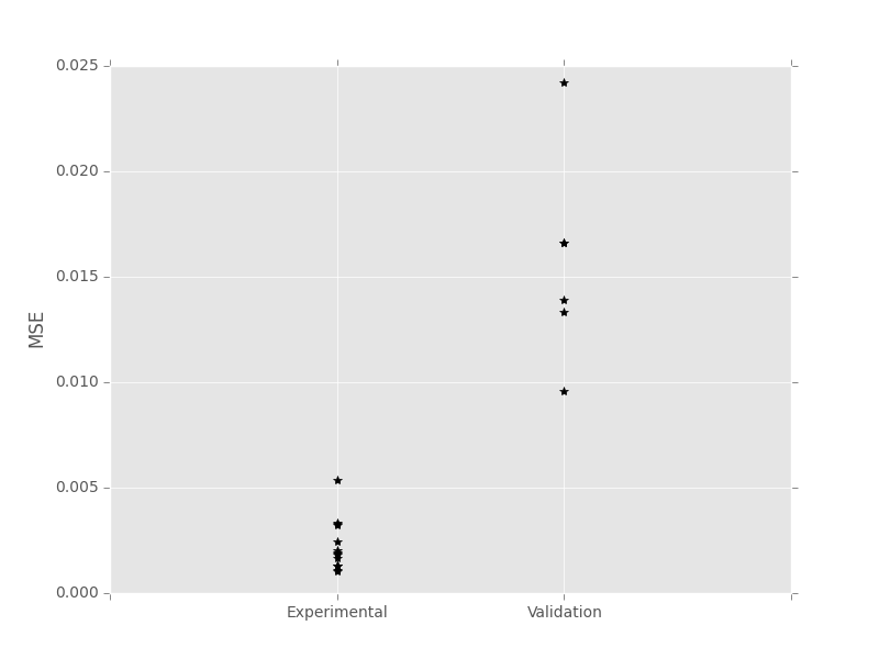 MSE for the Reconstruction:
Results
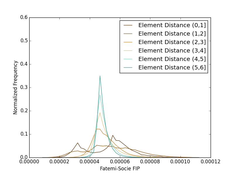
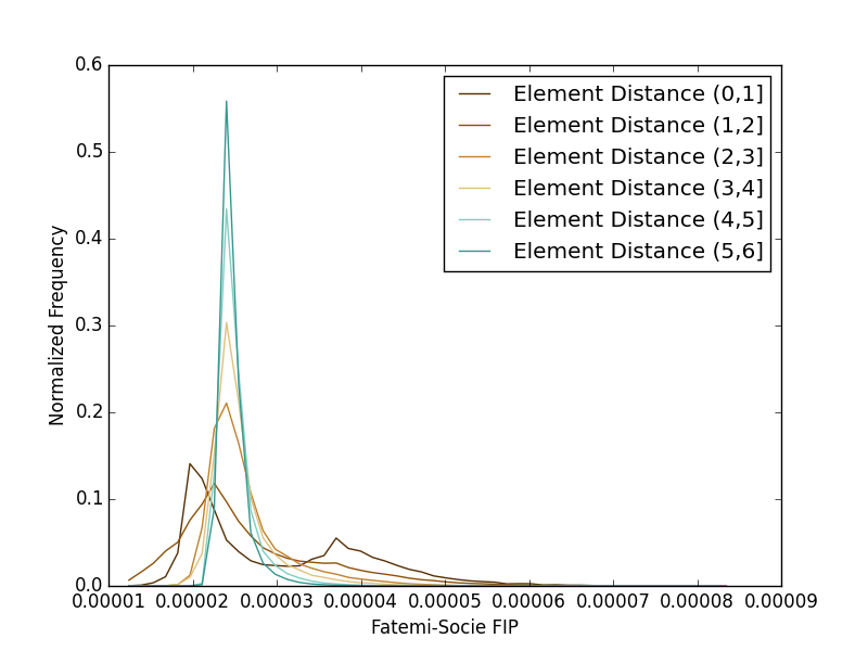
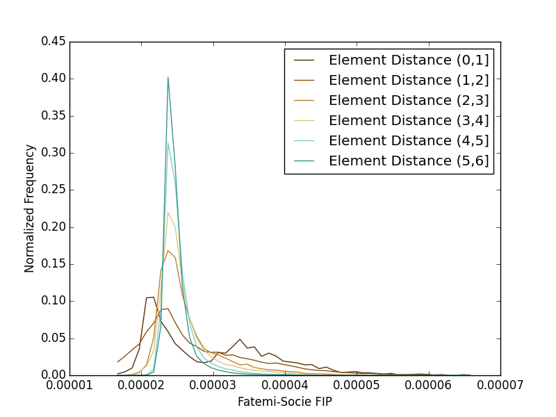
Seen below are the fatigue predictions for both shear and uniaxial loadings. Several interesting features become readily apparent in the plots here. The first is that both loading conditions do indeed quickly approach a far-field condition. For this reason, both plots are restricted to the first 6 spatial bins. Another feature is that both loading conditions appear to produce a bimodal distribution. The uniaxial distribution’s peak at the higher FIP value represents a larger relative intensification than that of the shear FIP distribution. The FIP values are still found to be higher in the shear loading condition, however, so while the intensification aspect is proved due to the anisotropic particle distribution, it is still insufficient to capture the discrepancy in our current fatigue model when compared to the literature results.
Shear:
 Uniaxial:
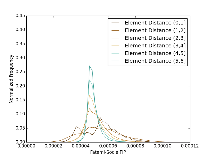
Finally, we apply a volumetric averaging method using a Gaussian filter to limit extreme value problems inherent in the discretized nature of our domain. Multiple standard deviations were examined with a final value of 0.5 elements. The overall distributions do not change substantially, and we draw the same conclusion of the uniaxial loading proving a higher intensification, but still lower overall fatigue damage response.
Shear:
 Uniaxial:
Conclusions
Our work does seem to provide some evidence that the anisotropic distribution of particles contributes to the knock down in fatigue lives for uniaxial loadings, however the effect is not pronounced enough to fully explain the difference from experimental results in the literature. There appear to still be missing physical basis to the models explored during this project and outside of it. This correction in fatigue lives could possibly come from more complex 3D interactions between crack and particles which will need to be modeled by different methods due to the contrast issue inherent with a very low stiffness crack in any material.
Acknowledgements
We would like to thank the following people:
- Dr. Kalidindi for his guidance in this project and the process of learning material informatics in general.
- Dr. McDowell for the encouragement to pursue new simulation methods.
- David Brough for letting us bounce ideas around and creating the pyMKS framework that we utilized extensively.
- Yuksel Yabansu for answering our questions about MKS.
- David Turner for producing the reconstruction code we utilized.
- NSF FLAMEL Program and NAVAIR for providing this class and project as well as the funding for our group
References
- Rollett, Anthony D., Robert Campman, and David Saylor. “Three dimensional microstructures: statistical analysis of second phase particles in AA7075-T651.” Materials science forum. Vol. 519. 2006.
- Fatemi, Ali, and Darrell F. Socie. “A Critical Plane Approach to Multiaxial Fatigue Damage Including out‐of‐Phase Loading.” Fatigue & Fracture of Engineering Materials & Structures 11.3 (1988): 149-165.
- Zhao, Tianwen, and Yanyao Jiang. “Fatigue of 7075-T651 aluminum alloy.” International Journal of Fatigue 30.5 (2008): 834-849.
- Harris, James Joel. “Particle cracking damage evolution in 7075 wrought aluminum alloy under monotonic and cyclic loading conditions.” (2005).