One of the main advantages of slot-die extrusion is that film thickness is easily controlled by the flow rate into the die and the substrate velocity:
where $Q’$ is the volumetric flow rate per unit width of the die, $u_w$ is the substrate speed, and $h$ is the wet film thickness. So for a given $h$ there is an infinite combination of $Q’$ and $u_w$. So how do you choose where to process?
There are physical limits on the setting combinations before defects such as air entrainment and break lines or process unsteadiness such as dripping occur due to the coating material properties. The region in which defect free production can occur is called the coating or casting window.
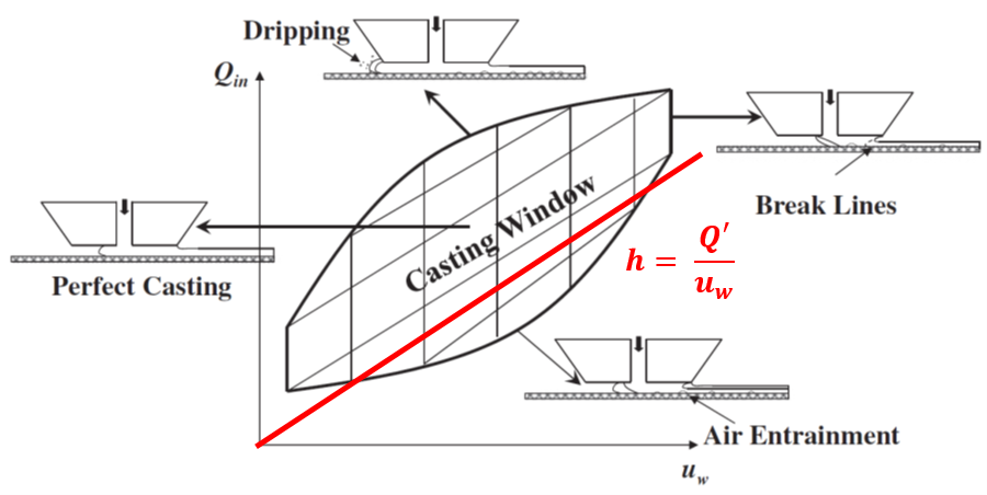
The figure above is a typical representation of the coating window with a line added for a constant film thickness. It is important to note that the edges of the coating window of this representation are dependent with the offset or gap height of the die above the substrate, H, and therefore this it is only a slice of the 3D region of the coating window.
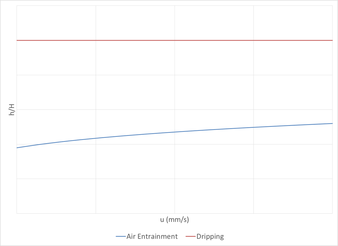
Since we know the film thickness desired and it relationship to Q’ and u_W, it is helpful during processing to have a representation of the coating window as only a function of speed and gap height. This is shown in the figure above with the gap height ratio since this is what we want to explore. The slower the speed the more margin between the two defect lines and the larger the range of height ratios that we can explore without causing defects in the membrane.
As introduced in a previous post, Project Plan, the velocity profile and therefor shear profile under the downstream die is a function of the height ratio. However the magnitude of the velocity and the shear is directly proportional to the substrate speed. So the larger the substrate speed, the larger the maximum shear, and therefore the larger the forces acting on the the particles.
So once again we come back to the original question since we have competing interests between the range of profiles and the magnitude of the forces with speed. Where do we want to process?
The choice of coating material and speed limitations of the slot-die roll-to-roll system used help simplify this choice for us. The air entrainment line can be found to be a function of the capillary number, which relates the relative influence of viscous to surface tension forces. Since NMP 20% CA has a relatively large constancy index as compared its surface tension, the speed at which we process must be kept low to avoid air entrainment. The lowest speed at which our system can currently be set reliably is ~0.4 mm/s and this was chosen so that a range of height ratios could be run before dripping would occur.
For the sample production, a constant target film thickness of h = 400 microns was selected to help increase the margins between the two defect lines (initial runs were tried at 300 microns but it was not possible to get a range of defect free coatings). The speed was set to u_w = 0.4 mm/s (fluctuations occured during testing) and the volumetric flow rate was to Q’ = 0.115 mm^2/s. The gap height was varied from a low of 200 microns to a high of 500 microns after which defects occurred. The table below summarizes the results.
| Run | H | u | Q’ | h | h/H |
|---|---|---|---|---|---|
| mm | mm/s | mm^2/s | |||
| 1 | 0.300 | 0.388 | 0.115 | 0.448 | 1.49 |
| 2 | 0.400 | 0.365 | 0.115 | 0.422 | 1.05 |
| 3 | 0.500 | 0.350 | 0.115 | 0.404 | 0.808 |
| 4 | 0.200 | 0.350 | 0.115 | 0.404 | 1.95 |
| 5 | 0.100 | 0.350 | 0.115 | 0.404 | 4.04 |
Due to the difficulty coating at the air entrainment boundary, the gap height ratios were higher that originally planned. It will be interesting to see how this affects the results!